Showing posts with label Design. Show all posts

Sunday, May 6, 2018

Moving forward with BMS!

With the success of the VSR Alternator Regulator I am now moving onto companion projects.  One that I had hoped would come up in the Open Source community was a good BMS targeted for HOUSE BATTERY usage as opposed to the Electric Vehicle (EV) segment.  Sadly, despite some brave words - no action has happened.   Plus some of the popular BMS devices have been purchased and taken off the market.

So, with that I have been working on a BMS and here is a draft design:


A few key notes:
  • It is designed using the STM32F072 CPU and will be programmed via the Keil IDE + CubeMX libs.   This is the standard development platform I am migrating to for better capability, and lower cost.  (However it is not as simple as the Arduino IDE to install and use...)
  • Design is has some unique capability to support a best-practice LiFeP04 house battery.  Notable features include:
    • Support for LiFeP04 main battery + small 'keeper' battery, typical an AGM starter battery.
    • Independent Voltage and Temperature sensing circuits for main and keeper battery
    • Support for battery disconnect of LiFeP04 (keeper battery remains connected)
    • Support for optional cell-level devices for Voltage, Temperature and balancing.

And of course this can be used with other traditional battery technologies, FLA, AGM, etc.   Just like the Alternator Regulator.

The concept of a 'keeper' battery when deploying LiFeP04 house battery banks allows for better systems management, especially during long periods of rest.   And with this will be the introduction of Battery Scenarios, where how a battery is treated is different on its current usage.  A prime example again is the LiFeP04 technology which desired to be at a modest SOC during extended periods of disuses (Think Winter Moorage).  This is a KEY difference in house oriented BMS vs. one designed for EVs.


Much more to come on this, including the cell level boards.  But I am hopping to have working systems by the end of this summer.

==============================================

I was also challenged to make a KISS BatMon (Battery Monitor), and here is an idea:
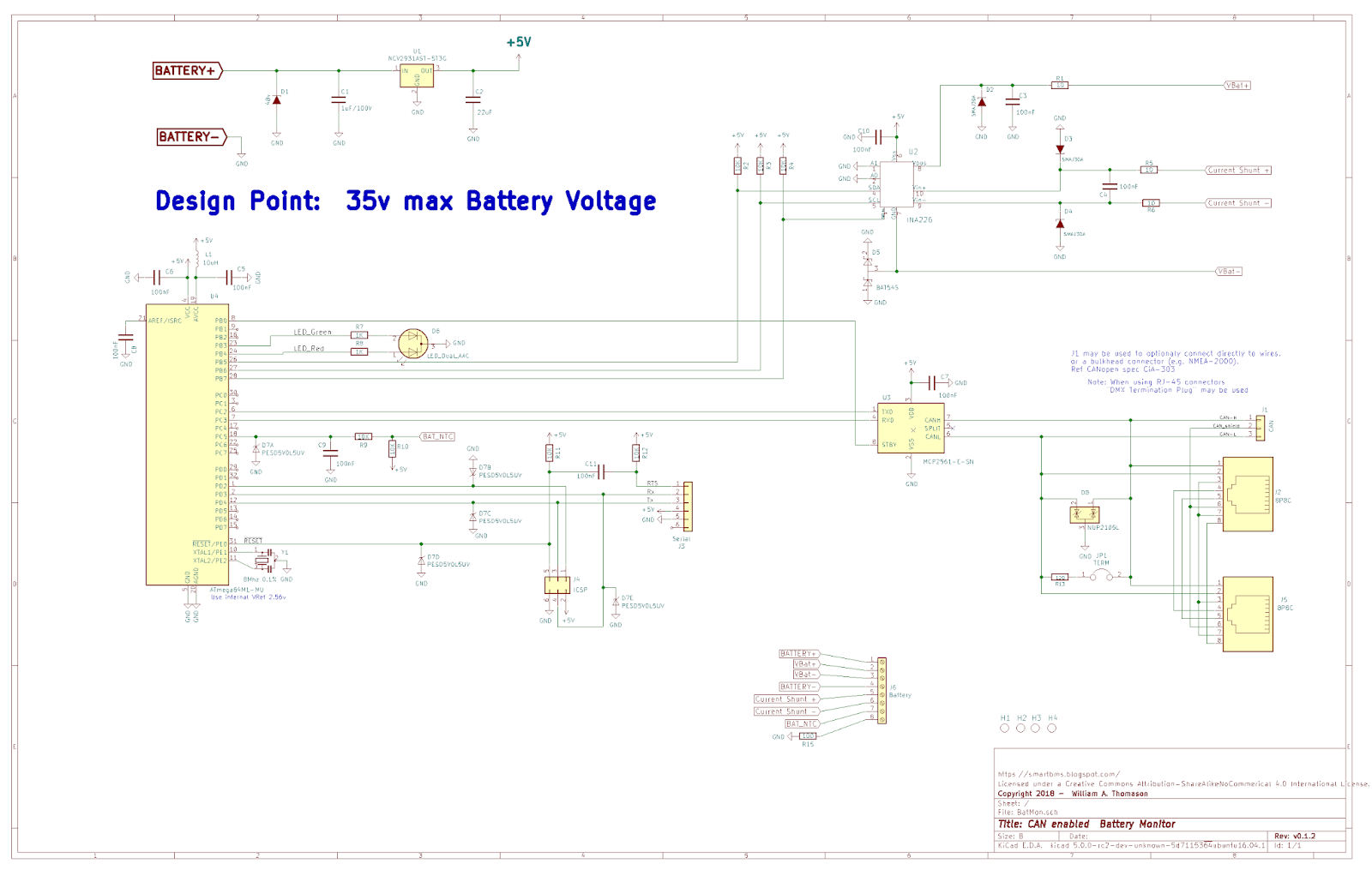


About as simple as I can make it - 3x ICs, a PS chip and a LED.  In addition to is function as an RBM it can also act as a 'port extended' for the regulator.  Based on the Arduino IDE, but I have stripped the built-in USB port, one would need to purchase a USB to Serial dongle (under $2 on Ebay).  BOM + PCB comes in around $10 for this device, but then there is the problem of getting it assembled at a reasonable cost.  When looking at it one wonders if there is a need for both  the BMS and this BatMon..   So for now it just an exercise, but who knows what may happen in the future..


Friday, February 27, 2015

Scope Creep - -

Kai had added a comment asking the question:

From what I understand, you also want to include cell-balancing for LiPos into this BMS. Don't you think this makes the whole project overly complex? There are so many dedicated devices for this task and only very few people are using LiPos on a boat or in an off-grid location anyways...BTW, I'm observing your projects for quite a while now. You are really doing a fantastic job, thank you! I'm in an off-grid situation with solar, batteries, an inverter and a 24v generator. A combination of your alternator regulator, bms and possibly also the mppt solar controller would be perfect for me!
All the best from Germany,
Kai

Good question, and as I started to type the reply it become obvious I could not keep my thoughts to a few lines.  So - the topic of Scope Creep. 

All projects have it.  There is an old, but perhaps not PC, saying in the Tech industry that at some point in time Marketing needs to come into the lab - gas all the Engineers and take what is setting on the bench; else nothing will every get to market.  My original DC generator started out as a simple regulator, expanded to include engine start/stop, then throttle control.  And hey, how about a remote panel as well!  So, what about this Cell balancing I poke at..

I think one will find we are rather close to a cross-over between traditional FLA batteries and LiFeP04.  Much depends on import duties and taxes, as well as if the LiFeP04 cells live up to their projected life expectancy, but given their wider usable range - as well as better charge efficiency, once might find they are very close to a Return On Investment cross over point with FLA..  This is a long way to say;  I think we will see more LiFeP04 deployments over the coming years.

But I also think there will continue to be lots of traditional lead-based storage out there as well.  Hence my general goal for all these projects:  Multi-chemestry, and 12..48v deployments.

But what about the Cell Balancing:  There seems to be a bit of dynamics in the LiFeP04 world to simply monitor, or have active balancing.  Will take time for that to settle.  My idea is to have as an option the ability to either monitor for imbalance, and/or provide for some type of active balancing capability.  This could range from simple monitoring using an existing modules such as the: http://www.cleanpowerauto.com/ modules. ( I have shared a few Emails with him.)  to doing an full monitor/balance.  

My work plan is to settle on a concept for the cell monitoring /balancing, as that will drive what hardware interface is needed in the main module.  Then develop the main module  (Battery MONITORING module) to work in conjunction with the MPPT controller and a future DC Generator  / alternator regulator.  Once all that is completed, can go back and add what every approach for the balancing / monitoring.  But in any case, it will be an add on option, and it is a 2nd tier work effort.  Just need to get a vision of direction today!


 (And again Thank you Kia for your questions:  Is nice to know some folks are out there)

Saturday, February 14, 2015

Sometimes waiting help - a lot...

Look what TI released just last month:  http://www.ti.com/product/bq34z100-g1


A kind of 'super INA226', it is built upon a small uC and included not only the Vbat and Amps measurement capability, but a column counter as well as a whole host of firmware to monitor and calculate a batteries SOC.  Still interfaced via I2C, and under $5

Am thinking to use this as the foundation for the monitoring portion of the BMS - add an Arduino based uC to provide CAN bus communications and controlling of the cell-management logic (See prior post:  "Central or Distributed") and external alarming - - - -  With some smart power management to reduce overhead..

Saturday, September 20, 2014

Refinement of draft Schematics - BMS + a draft CAN Alternator Regulator

Along with looking at CAN standards, I have been refining the draft schematics for the BMS, and crafted up an initial cut at a simplified CAN Alternator Regulator.   Here are a couple of snap-shots; higher resolution .pdf files can be found under the Schematics resource tab above.


Click for larger, or see .PDF file in Schematics resource tab above

Major changes to the BMS include:
  • Addition of small Switching PS for better energy usage.
  • Revised USB chip for more widely supported (driver wise) component.  Is also simpler to solder, and lower cost!
  • Improved CAN electronics, considering 'system wide' deployment.  There likely will be some additional enhancements / changes here - open to input from anyone with experience in this area.
I considered changing out the CPU for an integrated CPU/CAN device (ala, the 90CAN32), but am staying with the current solution as it appears to be able to provide lower power consumption.   In addition to more consideration on the CAN interface, I want to consider the optional BMS Cell loop - currently it is a Yes/No design in support of the Clean Power Auto cell monitors (http://www.cleanpowerauto.com/).  I want to consider how a simple protocol can be transferred over this same line to gain perhaps individual cell voltage status.  Maybe even enabling the OneWire standard - Or reusing the Auto industries LIN protocol (a kind of CAN lite) ??


I also drafted up a potential Alternator Regulator for use with the CAN system.  It is based on the Arduino Alternator Regulator (http://ArduinoAlternatorRegulator.blogspot.com/) with several key differences:
  • Battery measurements are utilize the BMS
    • There is no on-board remote battery voltage connectors..
    • Same of battery Amps, and Temperature
  • Eliminated Charge Pump (May add back), will cap max field drive to a duty cycle of 99.6%

Click for larger, or see .PDF file in Schematics resource tab above


 Some new features include:
  • Isolated CAN Bus interface
  • USB built in, just as the BMS is.

 It still supports 12v .. 48v batteries and fields, independent of each other.  It also includes local voltage sampling (at the Alternator) for the purpose of early detection of load-dumps, as well as fall back modes in the case of a failure in the BMS CAN bus communications.

Note that it has an isolated CAN bus, I will be key for any high current device (ala, charging sources) - as the voltage drop over even large cables can be significant.  And when paralleling the small signal gauge wires using in CAN wiring, one could end up trying to carry several amps of ground loop current.  Isolation prevents this situation.

Going forward I may look again at the Power Supply - perhaps also changing out of a switching mode PS. - one of the challenges is there is a need to pass though voltages under 12v to allow the FET driver to work.  So, and power supply design has to work in two modes:  Buck as well as pass-though....


Thursday, September 18, 2014

Reviewing potential CAN protocols

CAN is largely the hardware used to connected different nodes.  On top of that there are oh so many 'protocols' which can be carried, Wikipedia has a few nicely listed here:  http://en.wikipedia.org/wiki/CAN_bus#Higher_layer_implementations


From a higher level protocol I am looking for the ability for the BMS to broadly do two things:
  1. Effectively communicate the current status and health of the battery it is managing.
  2. Provide information useful to external charging sources for better coordination.
#1 is the classic:  Volts, Amps, temp, Ah, SOC, etc.  But for some battery types, notably LiFePO4, would include High Voltage and Low Voltage warnings as well as alarms and cut-off / faults.  #2 contains some of the same items as #1, but extends to include desired charge states, target charge voltages and currents, etc.   There needs to be some way to address multiple charging sources, ones of different capabilities and a way to prioritize them (ala, let Solar do the final top-off charging as opposed to running the generator).   And these need to be usable for batteries deployed in a house-bank usage, contrasting directly to those deployed in Electric Vehicles.

Of the ones I have looked at (not totally in depth), here is what I have found out so far:

SAE J1939-xx

  •  Set of industry specific standard developed for many segments:  Transportation, industrial, etc.
  • Special interest J1939/75: Generator and Industrial
    • Portions of this have been adopted by NMEA-2000.
    • Includes some concepts of battery instance and Charger Instance
    • Support 10mV / 100mA resolution
  • Strong / well developed standard
  • Closed, and costly.

OBD-II Mode#22 (aka: SAE J2190)

  • Variation of J1939 / OBD-II designed for EVs.  
  • Widely adopted by EV community for their BMS / Charger communications
  • Includes concept of BMS directed charging sources! 
  • Vbat resolution is 100mV, way too coarse for house battery usage.
  • Closed, and costly.

NMEA-2000

  • Built upon J1939, DeviceNet, and others - with marine specific extensions.
  • Implemented by some marine equipment suppliers (notable Victron)
  • Very fred DC/Battery PIDs defined - Most venders augment heavly via priority extensions..
    • There is a LiFePO4 working group that has been established.
  • Closed, costly.

RV-C

  • Open standard, targeting RV industry
  • Includes house battery and charger concepts.
  • Also included Generator, Autogen functions.. 
  • 50mV battery voltage resolution. . . .
  • Has many characteristics inline with J1939, but not a related standard. 
  • May be open to accepting extensions as needed
  • Open and Free!


CiA  / CANopen

  • Wide support and deployment, mainly in industrial applications.
  • Includes modules targeting Batteries (CiA-418) and Chargers (CiA-419)
  • Support for 1mV resolution!
  • Can not locate any Generator functions...
  • Semi-open/closed:  Free to use spec, membership needed for changes.


Each spec brings somethings, from BMS coordinated charging, cabling specs, generator integration, etc.  But some common problems include insufficient battery voltage resolution, closed / expensive standards to support.  Of them, my current thinking is along these lines:
  • J1939:  May have all that is needed, but clearly not open-sourced. 
    • using it would likely pick up to a large part NMEA-2000 compatibility.
  • J2190: Has key concepts for BMS directed charging sources, but some problems:
    • Grossly insufficient voltage resolution for House battery voltages (designed around 70-300v banks)
    • Assumes simple charge then discharge usage.  Does not support simultaneous use/charge modes.
    • Does not support different sized chargers.
  • NMEA-2000:  really just a repackaged J1939 spec with DeviceNet connectors.
  • CiA:  Promising.  May need some 'hacked in' extensions to fully support needs - lacks Generator support and not sure how would do different charging source coordination.
  • RV-C:   IF changes are accepted, can have what is needed.  Plus free licensing / usage.

At this point, I am going to continue to dig into information around the J1939-75 spec, I have started working with the RV-C team on some ideas for proposed changes, and I will keep in mind CiA as well. 

Does anyone out there have any thoughts / insights into this topic???


Sunday, August 17, 2014

Initial draft hardware design

I have posted into the Schematic resource tab above a .pdf file with an initial cut of a hardware design for a battery monitor.  Here is a low resolution photo as well (Look to the .pdf file to be able to see it better).


Refer to .pdf file in Schematics tab above for higher resolution view


Some highlights of the design:
  • Based on the Arduino Uno - compatible with its boot-loader, IDE, etc.:
  • Embedded USB controller vs. using external Service Port attachment
    • Initial layout also has service port, as no way am I hand soldering a QFN28 package)
  • CAN controller w/parallel hardware ports - allows easy Daisey chaining of devices on the CAN bus.
  • Measured Volts with a 1.25mV resolution, and Amps to 25mA depending on external shunt value
  • DIP switches to select battery ID as well as preferred default charge profile
  • Two feature out ports which can drive cutout relays, cooling fans, etc.  Able to do PWM control for verifiable speed.
  • Usable for 12v, 24v, or 48v batteries w/no hardware change.
  •  Connects to external Amp Shunt, max 80mV - and external battery temperate 10K NTC probe
  • PCB is 50x100mm in size
There are two additional pins left on the ATmega uC, trying to decide if there is a use for a feature-in port...

The PCB is laid out to support horizontal connectors as shown, but can also be populated with vertical connects as well.  Much will depend on how the mechanical case plays out.  Another option is to just solder wires directly to the PCB.

As this will be powered 24x7, also want to pay attention to power down modes.  Might be a challenge in keeping the Arduino environment, but as firmware is looked at will see.  I am thinking of drafting up some firmware, perhaps based off the Arduino Alternator Regulator's code - and mocking up a unit using a Uno + proof board.  but will not be able to play with this until next month as I will be traveling back to our boat to attend some long needed maintenance of her.