Monday, September 24, 2114

Welcome

Revised 3/5/2015

This project is a Battery monitoring (optional Management) System (BmS/BMS**) designed to be part of a larger system based on Arduino's IDE and utilizing CAN (Control Area Network) as a way to communicate and coordinate the charging of batteries from multiple sources.  I am mostly focusing on 'house' type storage batteries - mostly covering Marine, RV, and off-grid segments.   Over the next few weeks I will expand this blog some with details, but for now here is a summary of some of the goals of this project:

Overall Features:
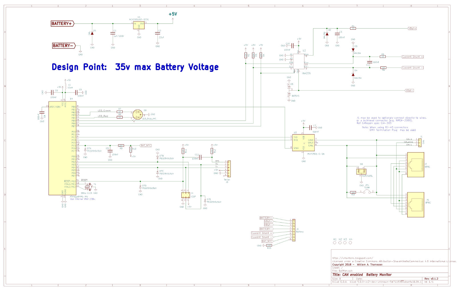
  • monitor battery voltage, temperature, and current draw (in or out).
  • Track total Wh's contained in the battery to provide SOC estimate
  • Communicate above with other projects on the CAN bus
  • Optionally interface with existing simple cell-level monitors and/or cell balancing, to protect out of balances batteries from over / under charge (delivering the full BMS - Battery MANAGEMENT System)
  • Output drivers to control external devices:  cooling fans, safety disconnects, etc.
I intend to migrate the Arduino Alternator Regulator as well as the Arduino DC Generator Engine Control and Regulator projects to make use of this BmS/BMS, along with creating a new Solar MPPT controller.  All with the idea of  simplifying installation by reducing the number of wires needed to one CAT-5 cable.   In addition, the BmS/BMS will be configured with its' batteries desired charge profile, and pass that on to any associated charging source(s).  In this way all the charging sources can work in a well coordinated fashion towards the needs of the battery.

                      http://arduinoalternatorregulator.blogspot.com/
                      http://smartdcgenerator.blogspot.com/
                      http://smartmppt.blogspot.com/


 Some likely future enhancements will include:
  • Inclusion of  a local panel display - showing a verity of status.
  • Ability to interface with larger tables / PCs to provide status as well as configuration of system.
 

All works are being released under the Creative Commons licensing agreement with the only restrictions around commercial use.  I have selected the Open Source KiCAD tool for Schematic capture and PCB layout and posted those CAD files.   Links at the top of this Blog provide details of each portion of this project.  Click on the Link-to-Files area to download the schematic and well as PCB layout and parts list (when posted).

The Design Elements section goes into more details of each sub-segment.

Comments and advice are always welcome!   It is my hope this project can be the basis for others works in intelligently controlling the care and feeding of batteries used in energy storage applications.


** To reduce, or perhaps increase, confusion I will try to use two nomiclatures:  BmS and BMS:  
  •  BmS = Battery monitoring System:  This will monitor the batteries status, SOC, as well as coordinate charging sources via the CAN.  It however will not have a key function of active cell balancing.  A BmS will protect the battery and inform the world as to its status and needs.
  • BMS = Battery Management SystemAdds to the above the ability to actively preform cell level monitoring and/or balancing.  Will likely be enabled by an add-on card (or cards) to connect to each cell providing details feedback on the cells status, and perhaps also allowing for some type of passive balancing.
I am making this distinction as from a hardware standpoint some battery technologies (e.g. LiFeP04) need additional ckts to protect them, specifically cell level checking - while others (e.g. FLA) do not.  Depending on the final  design it may be that an add-on component (or components) would be desirable to enable additional capabilities.  Till then, will make note of the BmS vs BMS - as the 1st work goal will be a BmS


Sunday, May 6, 2018

Moving forward with BMS!

With the success of the VSR Alternator Regulator I am now moving onto companion projects.  One that I had hoped would come up in the Open Source community was a good BMS targeted for HOUSE BATTERY usage as opposed to the Electric Vehicle (EV) segment.  Sadly, despite some brave words - no action has happened.   Plus some of the popular BMS devices have been purchased and taken off the market.

So, with that I have been working on a BMS and here is a draft design:


A few key notes:
  • It is designed using the STM32F072 CPU and will be programmed via the Keil IDE + CubeMX libs.   This is the standard development platform I am migrating to for better capability, and lower cost.  (However it is not as simple as the Arduino IDE to install and use...)
  • Design is has some unique capability to support a best-practice LiFeP04 house battery.  Notable features include:
    • Support for LiFeP04 main battery + small 'keeper' battery, typical an AGM starter battery.
    • Independent Voltage and Temperature sensing circuits for main and keeper battery
    • Support for battery disconnect of LiFeP04 (keeper battery remains connected)
    • Support for optional cell-level devices for Voltage, Temperature and balancing.

And of course this can be used with other traditional battery technologies, FLA, AGM, etc.   Just like the Alternator Regulator.

The concept of a 'keeper' battery when deploying LiFeP04 house battery banks allows for better systems management, especially during long periods of rest.   And with this will be the introduction of Battery Scenarios, where how a battery is treated is different on its current usage.  A prime example again is the LiFeP04 technology which desired to be at a modest SOC during extended periods of disuses (Think Winter Moorage).  This is a KEY difference in house oriented BMS vs. one designed for EVs.


Much more to come on this, including the cell level boards.  But I am hopping to have working systems by the end of this summer.

==============================================

I was also challenged to make a KISS BatMon (Battery Monitor), and here is an idea:


About as simple as I can make it - 3x ICs, a PS chip and a LED.  In addition to is function as an RBM it can also act as a 'port extended' for the regulator.  Based on the Arduino IDE, but I have stripped the built-in USB port, one would need to purchase a USB to Serial dongle (under $2 on Ebay).  BOM + PCB comes in around $10 for this device, but then there is the problem of getting it assembled at a reasonable cost.  When looking at it one wonders if there is a need for both  the BMS and this BatMon..   So for now it just an exercise, but who knows what may happen in the future..


Tuesday, April 7, 2015

Posted up v0.0.1 of monitor, but. . . .

Today I posted up an almost complete Battery MONITOR capable of measuring the battery voltage, amps, temperature as well as count its SOC.  Communications via CAN, USB and using the Arudino IDE.

I spent a lot of time coming to this point, mostly trying to get in some type of coulomb counter.  And in the end I have based this around the ATmega32HVB chip.   This part is design as a battery monitor/manager for Li cells, includes amp shunt, coulomb counter, and cell voltage readings.  Added to it is a SPI based CAN controller and a USB <--> Serial adapter (though will need to use SoftwareSerial libs, as the ATmega32HVB does not contain a UART)


(See Resource Tab above for .pdf file)


Over all I am not fully settled with this design.  The core chip is rather expensive ($11+), and after going through the voltage dividers for Vbat its 12bit ADC end up with a resolution of only 22mV.  Oversampling can help get this down to perhaps 6mV - fortunately the ADC is fast, but this is a long ways from the 16 bit ADC used in the INA226, where I also oversampled, and had much better resolution.  Interface to external cell monitors is incomplete as well.


Though I have posted this, I am not going to build a copy right away.  There is a lot of development work to be done on the MPPT controller, and I have other boards around that I can use to simulate a battery monitor, or even build one up.  Plus I want to think about this all some more.

Perhaps the biggest limiting factor at this point is usage of the Arduino IDE.  Without going to even more massive efforts (ala, what Intel has done -- among other) I was just not able to come up with a clean solution based on the Atmel uCs, and say the INA226 - close, but getting a coulomb counter capability was proving tough (again without going overboard and designing a discreet solution).  I would give the ATmegas32HVB based monitor a C+ grade.

Now - I also have been looking at the Freescale MM9Z1I638.  Has Volt, Amp, coulomb+ CAN and a UART for under $8.  Its 16 bit ADCs provide 1mV resolution, and there are 3 of them BTW - one for volts, one for Amps, and one for Temp.  It is a multi-die solution with all the analog separated from the digital stuff.  Plus it is targeted for the Auto industry, so it some with some extra hardening futures. I think this would make a much better core for the battery monitor / manager.

But it is not Arduino.  No simple IDE, need around a $50 probe to program, crippled free compiler, etc, etc..  


This is why I am a bit unsettled.  How important is it to keep the Arduino IDE for a project like this?  Goes beyond the monitor as well, PIC makes very nice uCs for the alternator regulator and Solar MPPT - but again, different development environment.


So - am a bit unsettled.  Given there is much to work on for now, will push this down the road some.  Perhaps anyone reading this has some thoughts?


Friday, February 27, 2015

Scope Creep - -

Kai had added a comment asking the question:

From what I understand, you also want to include cell-balancing for LiPos into this BMS. Don't you think this makes the whole project overly complex? There are so many dedicated devices for this task and only very few people are using LiPos on a boat or in an off-grid location anyways...BTW, I'm observing your projects for quite a while now. You are really doing a fantastic job, thank you! I'm in an off-grid situation with solar, batteries, an inverter and a 24v generator. A combination of your alternator regulator, bms and possibly also the mppt solar controller would be perfect for me!
All the best from Germany,
Kai

Good question, and as I started to type the reply it become obvious I could not keep my thoughts to a few lines.  So - the topic of Scope Creep. 

All projects have it.  There is an old, but perhaps not PC, saying in the Tech industry that at some point in time Marketing needs to come into the lab - gas all the Engineers and take what is setting on the bench; else nothing will every get to market.  My original DC generator started out as a simple regulator, expanded to include engine start/stop, then throttle control.  And hey, how about a remote panel as well!  So, what about this Cell balancing I poke at..

I think one will find we are rather close to a cross-over between traditional FLA batteries and LiFeP04.  Much depends on import duties and taxes, as well as if the LiFeP04 cells live up to their projected life expectancy, but given their wider usable range - as well as better charge efficiency, once might find they are very close to a Return On Investment cross over point with FLA..  This is a long way to say;  I think we will see more LiFeP04 deployments over the coming years.

But I also think there will continue to be lots of traditional lead-based storage out there as well.  Hence my general goal for all these projects:  Multi-chemestry, and 12..48v deployments.

But what about the Cell Balancing:  There seems to be a bit of dynamics in the LiFeP04 world to simply monitor, or have active balancing.  Will take time for that to settle.  My idea is to have as an option the ability to either monitor for imbalance, and/or provide for some type of active balancing capability.  This could range from simple monitoring using an existing modules such as the: http://www.cleanpowerauto.com/ modules. ( I have shared a few Emails with him.)  to doing an full monitor/balance.  

My work plan is to settle on a concept for the cell monitoring /balancing, as that will drive what hardware interface is needed in the main module.  Then develop the main module  (Battery MONITORING module) to work in conjunction with the MPPT controller and a future DC Generator  / alternator regulator.  Once all that is completed, can go back and add what every approach for the balancing / monitoring.  But in any case, it will be an add on option, and it is a 2nd tier work effort.  Just need to get a vision of direction today!


 (And again Thank you Kia for your questions:  Is nice to know some folks are out there)

Saturday, February 14, 2015

Sometimes waiting help - a lot...

Look what TI released just last month:  http://www.ti.com/product/bq34z100-g1


A kind of 'super INA226', it is built upon a small uC and included not only the Vbat and Amps measurement capability, but a column counter as well as a whole host of firmware to monitor and calculate a batteries SOC.  Still interfaced via I2C, and under $5

Am thinking to use this as the foundation for the monitoring portion of the BMS - add an Arduino based uC to provide CAN bus communications and controlling of the cell-management logic (See prior post:  "Central or Distributed") and external alarming - - - -  With some smart power management to reduce overhead..

Tuesday, February 10, 2015

Central or Distributed?

Now that I have made some progress on the MPPT controller, I have been thinking ahead towards the BMS.  At 1st I had in mind to simple create a Battery MONITORING System, as opposed to a Battery Management System - with perhaps the biggest delta being if one is able to recognize, and actively rebalance batteries who's cells have drifted apart.  (Perhaps most commonly seen in LiFeP04 deployments).

This extra capability requires some attachment to each cell in a battery, and there are two ways to do it:

  1. Have a master-controller, and then on each cell place a module to measure and report back status.
  2. Still have a master-controller, but instead of communicating with individual cell monitoring/management devices, have a centralized one co-exist with the master-controller. 
As always there are ++ and -- to each approach.  The Distributed approach keeps the cost of the master-controller down when there is no need to actively monitor / manage at a cell level.  Perhaps only some extra logic is needed to provide an 'expansion' port.  But the distributed system might be a bit more costly, as it would require a small uC at each cell - and there are those who comment that placing something on each cell will also, over time, cause the cells to go out of balance due to slight variations in the cell level boards...

The centrally located one is perhaps a bit cleaner, as only one (or two) wires need to be routed to the junction between each cell - as opposed to a small board and some communication wires for the distributed option.  And one could do an expansion board for the centrally located master as well, or just integrate the logic into the master and perhaps make it a depopulation option....


I think this comes down to two approaches for this project.  A Master controller with CAN, overall battery voltage and  current monitoring and then either:
  • A common Cell module which can monitor voltage as well as temperature - communicating back likely over a LIN serial network.  --OR--
  • An expansion board which attached to the top of the master controller and support 6 batteries.  Communicating perhaps via the SPI bus, and only able to monitor voltages of each cell (no temperatures).  Should have the ability to add up to 4 expansion boards, for 24 cells (48v battery support being a common goal across all these projects)
Either would also include the option of enabling resistive "bleed-down" cell balancing if desired / needed.

Perhaps I will mock up a couple ideas and price them out - see if that gives any additional insight.

Friday, January 30, 2015

Still Here Post

Just a quick post to let any know this project is still alive, but taken a back set to the solar MPPT controller as well as work to enhance the core regulator engine in the External Alternator Regulator as well as the DC Generator projects.

My timeline is to complete the above tasks, bring the MPPT controller to a stable state, and then begin working on a CAN based communications protocol based on the open  RV-C spec.  Then work will resume on this BMS system, with perhaps two variants:  Monitoring only, and monitoring combined with cell balancing capability.


links:

http://smartMPPT.blogspot.com/

http://arduinoAlternatorRegulator.blogspot.com/

http://smartDCgenerator.blogspot.com/

http://rv-c.com/